| |
![]()
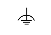
Some PROFIBUS devices feature a functional grounding terminal. Connect the grounding terminal of the PROFIBUS station to the system ground. The grounding terminal is identified by the symbol for grounding .

- The Protective earth terminal is independent from this and must always be tied to the protective earth of the system..
- For other devices, the grounding is carried out via the DIN-Rail. For this reason, you should also ground DIN-Rail.
- Use copper cables with an appropriate cross section (> 2.5 mm²) for the grounding connection of the PROFIBUS stations. Grounding cables generally feature a green-yellow insulation. In some countries, the green-yellow identification is mandatory (green in the US).
|
